The Ydrive
The Ydrive (named after its resemblance to the letter Y) is a Variable Velocity Device. It consists of four independent arms each connected to a central axis. Each arm has a ball, of mass m, at its outer end. As a VVD, the angular velocity changes during each cycle. This is accomplished by changing the velocity V of each arm, while keeping the radius constant.
We have seen that a VVD has a problem caused by the reaction
of the accelerating force in the system. This reaction creates a
negative impulse that adds to the negative centrifugal force
impulse. This exactly matches the positive centrifugal force
impulse, causing the net impulse to be ZERO. So, the only way to
achieve a positive net impulse would be to prevent this reaction
force from acting in the system. This may seem impossible, but
it's exactly how the Ydrive works. In the Ydrive, the arms are
paired in such way to allow each pair to have its arms
interacting with the other pair. This may be a little confusing,
but its the real magic of the Ydrive. The change in the
tangential velocity of each ball is caused ONLY by the
interaction with the other pairing ball. Therefore, each pair
acts as a closed system, within which Newtonian actions and
reactions take place. Since each ball has the same mass, any
interaction between them will produce symmetric results. While
one will increase in tangential velocity, the other will
decrease. It may be difficult at this point to visualize what is
going on between the two sets of paired balls as they
simultaneously rotate around the system axis. If you take the
rotational plane around the axis as a reference, you will see one
pair of balls going away from each other as the other pair of
balls is going together. All this is happening as the four balls
move in a circular trajectory around the system axis. But if you
take a static look at the plane of rotation, you will see what is
shown in the animation on top. Numeric calculations have
demonstrated a significant resultant impulse aligned to the y
axis pointing to 270 degrees direction. The math is not complex,
and has shown a net impulse of
Math / Graphics analysis
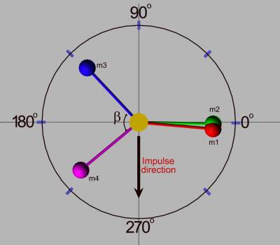 Fig.
2 Ydrive parts.
Fig.
2 Ydrive parts.
To start analyzing the Ydrive, we will need first to describe its parts and how they interact each other. The fig. 2 shows its main components at time t-dt from their starting condition. The masses m1 and m2 are almost overlapping, the masses m3 and m4 are at an angle Beta to each other. This angle will play an important role in the device, as we going to see. As the system starts rotating counterclockwise, after a given time t0, m3 and m4 will start approaching each other by the action of a internal force. At the same time, m1 and m2 will start distancing each other by the action of the same internal force. This cycle will complete at each half turn of the system, and then it will be back to the same formation, but this time m3 and m4 will be overlapped and m1 and m3 will be at angle Beta to each other. (Note that the wider side will always be to the left as in fig.2)
The best way to proceed in our analysis will be to fix some values and trace the centrifugal force curve of each ball mass. Then, as we have done before, we will study the areas of the curves numerically and see how they add together. Lets fix the parameters:
m1 = m2 = m3 = m4 = 0.05 kg
r = 0.1 m
w0 = 100 ; angular velocity of the central axis.
beta = Pi/2 ; arm maximum angle.
theta = Pi beta ; angular position where the arms start moving.
t0 = theta/w0 ; time needed for the axis to reach the angular position theta.
t1 = beta/w0 ; time needed for the arms to move beta/2 radians.
In this analysis, the angular velocity of the central axis, (w0), will be kept constant. The time t0 is the point where the arms will start moving. Then, after time t1 the arms will be at final position within the half cycle.
First of all, lets calculate alpha, the angular acceleration resulting from the action of the internal force between each arm pair. Since each arm will move beta/2 in time t1 we can say:
beta/2 = ½ alpha * t1^2
alpha = w0^2/beta
Since alpha will only exist after theta position, I will multiply alpha by a factor that will keep it null up to time t0. So, alpha will be given by:
alpha = w0^2/beta ( (1+ (t-t0)/(sqrt(t t0))^2)/2)
Note that the factor multiplying alpha is
only a mathematical technique to control the value of alpha
as desired. This term will be ZERO up to t
= t0 and then change to
Lets now proceed to calculate the angular velocity of each arm, w1, w2, w3 and w4.
w1 = w0 + alpha * (t-t0)
w2 = w0 alpha * (t-t0)
w3 = w2
w4 = w1
Note that the term (t-t0) guarantees that only the proper time interval will be used to compute the change in velocity. Before t= t0, alpha will remain zero as demonstrated above. Lets now calculate the angular position a1, a2, a3 and a4.
a1 = w0 * t + ½ alpha * (t - t0)^2
a2 = w0 * t - ½ alpha * (t - t0)^2
a3 = (Pi - beta/2) + w0 * t + ½ alpha * (t - t0)^2
a4 = (Pi + beta/2) + w0 * t - ½ alpha * (t - t0)^2
We see that unlike a1 and a2, a3 and a4 have one additional term. This is because at time t=0, a3 and a4 are not at zero angular position, so we have to include their position in the equation. We are now ready to calculate the centrifugal force in each arm.
F1 = m * w1^2 * r * Sin[a1]
F2 = m * w2^2 * r * Sin[a2]
F3 = m * w3^2 * r * Sin[a3]
F4 = m * w4^2 * r * Sin[a4]
The multiplication by the Sin[ ] of the angle will restrict our analysis to the Y axis, since the component at the X axis could be canceled by superimposing two devices rotating opposite to each other. So the X component will not be considered
Lets now see a plot in time of the force F1, F2, F3 and F4 as a function of time.
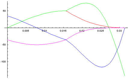
We can see that the curves of F1,(red) and F2,(green), overlap up to t = t0 as expected, then they split. F1 decreases to zero as F2 initially increases fast then decrease to a very high negative peak. F3 and F4 will exhibit similar behavior , but look that they never crosses the ZERO line to the positive side. Lets now see a plot of the resultant force, the summation of all for forces. As done before, Ive filled the areas equivalent to the positive (red), and negative,(green), impulses.
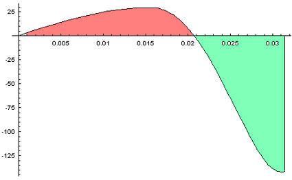
We can easily see that the green area is far bigger than the
red one, representing a impulse in the Y axis
towards the 270 degrees direction ,(6 hours). A numeric
integration has shown a result of
If this results can be proved correct, and no other hidden force is acting in this system counteracting the found resultant, then we have mathematically proved that it is possible to produce linear momentum as a result of the unbalance of forces inside of a "closed system".